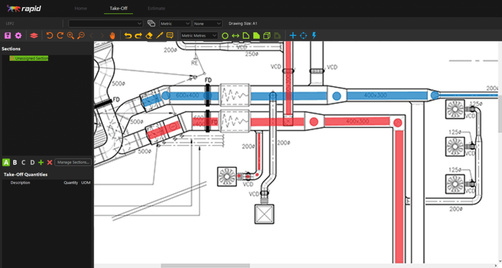
DUCTWORK DESIGN APP PROFESSIONAL
Perfect for architects doing small residential jobs to HVAC engineering consultants and contractors doing large commercial projects.ĭUCT was designed and verified by professional mechanical HVAC engineers for air conditioning and fan ventilation applications. If you plan to use DUCT for work why not claim the cost of DUCT back as a work expense?ĭUCT is simple and effective for anyone to use. All size options and other performance values are visible at once, just like an original ductulator.Īvailable in SI units and Imperial units. Just touch and move up and down to match the properties you want - just like the real thing. Save time and money with DUCT as there is no typing in values like other ductulator apps. With DUCT, the simplicity and rapid sizing of the classic slide ductulator is now in your pocket.ĭUCT uses the same rectangular equivalent method as your standard paper ductulator except all rectangular dimensions are recalculated from Huebscher’s equation. It has many modules like duct designs, business solutions, etc.

In this example, we have set the Finished Floor to Bottom to 117". Set the Finished Floor to Top/Bottom to match the height of the molding polyline.Set the Width, Height, and Depth as needed.įor these types of symbols, if the size of the duct was modified, it's best to check the Retain Aspect Ratio check mark before making any modifications.On the General panel of the Fixture Specification dialog that displays:.Using the Select Objects tool, click on the fitting to select it, then click the Open Object edit button.

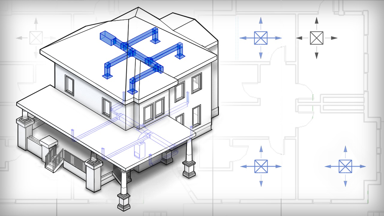
If necessary, you can temporarily disable snap settings by holding the Ctrl/Command key on your keyboard while placing the fitting. In this example, we will be using the Cross fitting found within the 90 Degree Transitions subfolder.
DUCTWORK DESIGN APP MANUAL

This can be used to control where the molding is generated, and it can then be selected and moved in Plan View to align it with the other molding polylines. Conversely, if there are no surfaces for the polyline to attach to (such as drawing and converting the polyline outside of a room, away from other objects, or in a Backclipped Cross Section where no other surfaces exist), the molding polyline will generate 12" from the cross section plane.3D Molding Polylines behave similarly to, but not exactly like standard Molding Polylines, and will automatically attach to any surface (such as a wall) that the line crosses over in the elevation view. When a CAD Line is converted in an elevation view it can only be converted to a 3D Molding Polyline.

If vertical ducts are required, some special considerations should be made:


 0 kommentar(er)
